Determination of Flexural Strength of Palisade Fencing Pales
Method for the determination of characteristic flexural strength of steel palisade fencing pales.
Apparatus
The test shall be carried out using any reliable machine of sufficient capacity and capable of applying the load continuously and vertically. The device for applying the load shall consist of two radiused supports and a load-applying roller or radiused pad (see Figure 1).
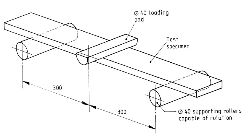
Figure 1: Arrangement of loading test specimen
All rollers, radiused loading pads or blocks shall be manufactured from steel and shall have a circular cross-section with a diameter of 40 mm ± 2 mm; they shall be at least 10 mm longer than the width of the test specimen of palisade panel pales.
The distance between the outer supports, shall be equal to 600 mm. All rollers shall be adjusted in their correct position with all distances having an accuracy of ±1.0 mm.
Load control
The machine shall be capable of applying the load uniformly without shock using manual or automatic control.
Load scale indicators or digital displays
- The machine shall be provided with either:
easily read dials or scales which conform to BS 3693; or electrical load indicators, which shall include a visual display.
- The machine shall conform to grade 2.0. The machine scale range shall be chosen so that the palisade pales specimens can be tested in the part of the range which is certified accurate to ±2% of the indicated load.
- The grading of the machine shall not be affected by variations in mains supply voltage or frequency of ±10% from the normal value to the machine.
Test specimens of palisade fence panel pales
- Dimensions: palisade pales cut to 1 000 mm ± 20 mm in length.
- Sample size: six.
Test procedure
Wipe clean the bearing surfaces of the supporting and loading members and wipe any loose surface deposits off the specimen. Place the specimen in the machine, correctly centred and with the
longitudinal axis of the specimen at right angles to the supporting and loading rollers. Do not use any packing between the specimen and the rollers. Apply the test load when all loading and support members are in even contact with the specimen. Discard without testing any specimen which, due to twist, has a clearance of more than 1.0 mm from any contact position under zero load.
Establish a datum for deflection.
Apply the test load steadily and without shock over a period of not less than 30 s. When equilibrium has been achieved measure and record the deflection at the centre of the span.
Using a new test specimen each time, carry out the test three times with the face of the pale uppermost and three times with the back of the pale uppermost.
Test report
- Information to be provided to the test laboratory
- the date, time and place of palisade fence pales sampling and the sample identity number;
- the name of the supplier.
- Information to be provided by the test laboratory
- identification (including palisade pale profile);
- condition when received;
- date of receipt;
- measured length, thickness, width and depth of palisade fence panel pales;
- any surface preparation;
- deflection at the specified loading;
- date of test;
- other remarks, as necessary.
- Palisade Fencing
- General Palisade Fences
- Security Palisade Fence
- Palisade Gates
- Palisade Pales
- Palisade Posts
- Palisade Rails
- Palisade Fittings

We provide a series of customizable palisade fencing products including palisade fence panels, palisade gates, palisade pales, palisade rails and fittings to build your own high security system.